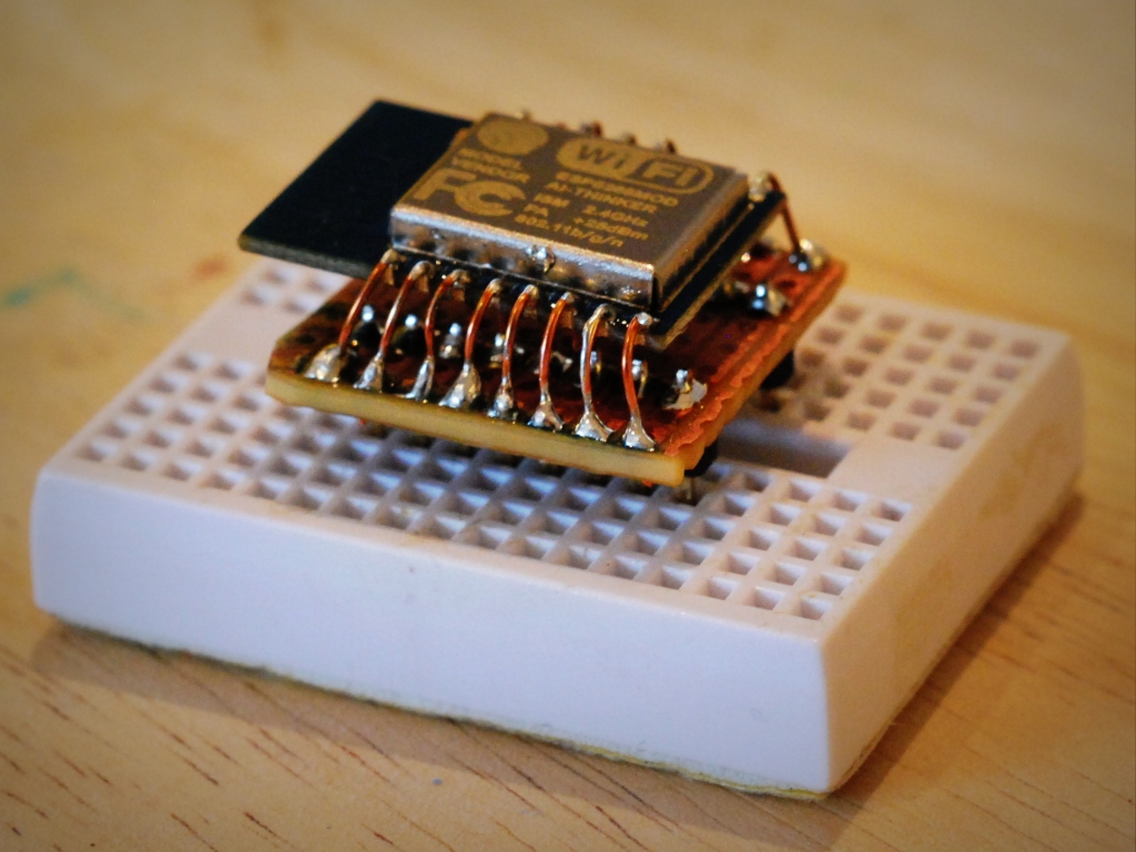
I needed to prototype the soil moisture sensor on a breadboard, but as we all know, the ESP8266’s in their many different guises aren’t the most breadboard friendly modules you’ll ever come across. The secret here (for me anyway) was some tripad stripboard that I had lying around. I dropped two rows of 8pin headers into the breadboard so they were either side of the central divide, and cut a piece tripad big enough to allow the ESP-12 to sit on it, while the headers sat below. I pushed the tripad onto the top of the headers that were in the breadboard and soldered them on.
I then got some thin copper wire and soldered about 15mm to each contact of the ESP-12. This was fiddly, but didn’t take nearly as long as I’d thought it would. (In the photo you can see that I used a bit of White tape to protect the ESP-12 from the grip of the crocs on my helping hands.) Once soldered, I bent the wires on one side nearly 90º downwards and fanned them out a bit so they would fit through the 2.54mm spacing on the tripad. These were then soldered in place. Next, was the other side, this had to be bent a bit more aggressively, and then fanned out again to get through the holes on the triboard, and when I’d got the module sitting nearly level, I soldered these in too.
I think it looks surprisingly tidy for my work, the module sits above the tripad by about 4mm suspended on rows of copper legs. It works great too. allowing for a rapid breadboard prototype to be built.


